CHILL Receivers
This is a description of the receivers and downconverters used at CHILL. It also includes a description of the digitizer hardware.
Main Receivers
The main receiver channels for the CSU-CHILL radar consist of a pair of separate, matched receivers. Each receiver can be independently operated, with a dedicated receiver for each polarization channel. In alternating mode, the receivers are switched through a transfer switch. Thus, in alternating mode, one digitizer channel is a copolar receiver, while the other is the crosspolar receiver. The LNAs are not switched in order to prevent losses from the transfer switch from affecting the noise figure of the receiver.

A sample receiver gain calibration curve is shown below. The noise floor (or minimum detectable signal), after interpolation, is approximately -113 dBm. This curve is measured by injecting a BITE pulse of a known power into the reference plane and measuring the output power from the digitizer.
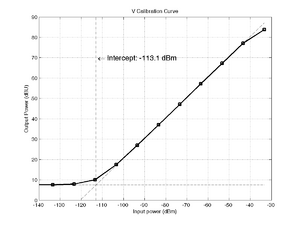
Image Rejection Filter
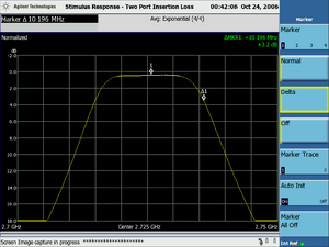
The Image rejection filter is a 20 MHz bandpass filter implemented as a stub-tuned waveguide filter. This filter rejects signals at the radar's image frequencies (2825 MHz and 2625 MHz), and also prevents out-of-band interference from entering the LNAs. Out-of-band interference can cause the LNA to saturate or generate undesirable intermodulation products which are subsequently difficult to filter out. Thus, this filter is used even though it introduces about 0.5 dB loss before the LNAs.
LNA and Receiver Protectors
The receiver pickoff point from the circulators (see the figure in the Transmitter description) can still carry high-level RF signals, since the circulator only isolates up to about 10 dB. The remaining high power is attenuated using a CPI/Varian VDS1142 gas-discharge T/R tube. The tube uses a radioactive salt to maintain partial ionization of a gas-filled cavity. When a high RF power is incident on the protector, the gas ionizes to form a conductive plasma, which discharges the RF power and protects the sensitive LNAs from damage.
The LNA used is a low noise figure, narrowband type (NF=0.8dB) from Miteq. It has a gain of 33dB, and an 1 dB compression point of +10 dBm. The high gain keeps the overall noise figure of the receiver low. It is adversely affected, however, due to the losses in the protection tube and the waveguide run from the antenna.
The LNAs and first mixers of the two channels are maintained at a constant temperature of 20° C using a Peltier cooler. This minimizes the effects of thermal drift from affecting the differential gain between the two channels.
Transfer Switch
This is a high-speed GaAs crossover (transfer) switch. It allows either LNA to be connected to the downconverter inputs. In most polarization modes, the transfer switch is left in a pass-through mode. In alternating (VH) mode, however, the transfer switch is moved to the cross-over mode when the V transmitter fires. Thus, the downconverter and digitizer channel marked "H" is always the copolar channel in VH mode, while the channel marked "V" is the crosspolar channel. This is done to keep the copolar signals restricted to one channel. Ideally, this switching would be done before the LNA, however the additional loss introduced by the switch cannot be tolerated here.
Downconverters
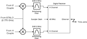
The downconverters are a single-stage downconversion to the final IF at 50 MHz. Level-10 mixers are used, meaning they can tolerate a maximum of +10 dBm at their inputs before saturating. This sets the saturation point (before the LNAs) at approx. -20 dBm. The amplified signals are mixed with the STALO frequency at 2.775 GHz to generate the LO frequency at 50 MHz. The amplifiers following the mixers have a bandwidth of approximately 1 GHz, which rejects the other mixer product at 5.5 GHz.
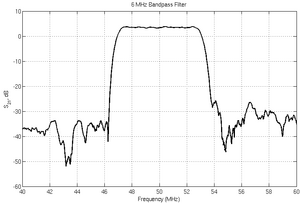
The IF signal is bandpass filtered to a 6 MHz bandwidth, this is an antialiasing filter for the digitizers. The antialiasing filters are implemented using a SAW filter, with relatively sharp cutoff characteristics. This prevents out-of-band signals from interfering with the digitizer operation. It is also phase-linear within the passband, and is suitable for use with pulse compression waveforms.
Attenuators are provided at this point to adjust the system gain to optimize the digitizer's dynamic range. Projects that require measurement of low-SNR phenomena such as clear-air echoes can specify a low attenuation here, while projects that require wider dynamic range can use a higher attenuation. The radar can execute a calibration cycle after a change of attenuator settings.
Transmitter Sample Receivers
The transmitter sample receivers are a separate set of receivers used to downconvert a sample of the transmitter pulse. This channel is not passed through the main receivers, since the high power from the transmitters would likely saturate the receiver, and any microwave switching ahead of the receivers to prevent this would introduce additional losses. A separate pair of digitizers is used to capture these signals. These samples then replace the first few samples from the main digitizer, which are not useable since they are contaminated by transmitter pulse leakage through the circulators and T/R tubes.
Digitizers
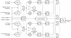
The digitizers used in the radar are based on the commercially available ICS-554 digitizer from ICS Ltd. This is a PMC card with four transformer-coupled ADCs, a 3 Million gate Xilinx XC2V3000 FPGA and a PCI-bus interface ASIC. The FPGA is loaded with customized logic which implements a digital downconverter and filter, and framing logic for generating headers embedded within the data. The headers include information such as the antenna position, transmitter state, etc. The PMC card is mounted on a PCI carrier board plugged into a Supermicro dual Xeon server machine running the time series server software. The server is hosted on the Linux platform.
ADC
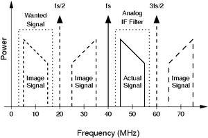
The ADCs used on this board is the AD6645 from Analog Devices. It is operated at a sampling rate of 40 MHz, while sampling a 50 MHz IF signal using undersampling (also called Sub-nyquist sampling). The figure below illustrates the principle. By undersampling, the input signal is within the third Nyquist zone of the digitizer. It gets aliased back down to the first zone, centered at 10 MHz. Note that the analog antialiasing filter in this case has a bandpass response, and prevents energy from other Nyquist zones (such as at 30 MHz or 70 MHz) from interfering with the signal at the wanted zone.
FPGA
The digitizer's onboard FPGA implements a programmable wideband digitial downconverter. The downconverter NCO frequency is set to 10 MHz, which shifts the input signal (also at 10 MHz, due to the undersampling performed by the ADC) down to base-band using the quadrature mixers. The output of the mixers is filtered and decimated by a factor of 8. This output, at a 5 MHz sampling rate, is available for processing by the host. In addition, the data is further filtered and decimated down to a 1 MHz rate. Both streams are available simultaneously to the software. The filters are programmable, and are of 64 and 128 taps, respectively. While filtering both channels, the FPGA executes approximately 2.2x10⁹ multiplications per second.
The FPGA inserts headers into the data stream every time it receives a transmitter trigger. The structure of the header is shown in the figure below. Since the headers are attached to the data in hardware, subsequent hardware/software buffering performed by the bus interface ASIC and the ICS device drivers does not affect synchronization.
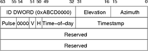
The time-of-day and timestamp are derived from the GPS reference. The timestamp has a resolution of 25 ns.
Acquisition Server
The Acquisition Server software is responsible for obtaining data and headers from the digitizer board and making it available for other software, such as the moment calculation software, time series archivers, etc. It supports multiple connections simultaneously, which allows simultaneous archiving of time series data along with real-time processing. The server also obtains control data blocks from the radar controller and multiplexes them with the time series data. This way, all downstream software is aware of the radar operating state without the need for a separate communication channel.
Further information about the acquisition server can be obtained from its software documentation