FrontX

| Deployment Type | Trailer-mounted |
|---|---|
| Frequency | 9.41 GHz (X-band) |
| Operating Modes | ATSR, Single-Polarization |
| Range Resolution | 30-150m |
| Typical Range | 60 km |
| Antenna | 1m (1.5x2.6°) |
| Transmitter | 64 T/R modules (70W) |
| Receiver | CSU DXR |
Front-X is an X-band dual-polarization phased array radar demonstrator radar. The objective of this radar system is to demonstrate dual-polarization capability and to study the limits of phased array antennas on polarization measurements. The radar is a test-bed to validate new radar waveforms, pulsing schemes, signal processing algorithms and scanning strategies that take advantage of electronic beam steering. The radar was developed in partnership with FirstRF corp.
The radar consists of an X-band dual-polarization active phased array antenna that generates a fixed beam in one axis and can scan electronically in the other axis. The antenna array is composed of 64 radiating elements, each driving a patch array antenna that develops a fixed pattern 2.6° wide. Beam width is 1.5°x2.6°, with over 90° electronic scan range. Transmit peak power is 70 W, with a duty cycle up to 33%. Antenna polarization is switched between horizontal and vertical on an alternating basis. The antenna instantaneous bandwidth is 30 MHz tunable over the 9.21 - 9.61 GHz frequency range.
Technical Overview
Block Diagram

The radar block diagram is shown above. Most of the radar electronics is housed in the Antenna-Mounted Electronics Enclosure, including the digital exciter/receiver (DXR) and the radar interface module. The interface module allows the DXR to control the phased array antenna according to pre-programmed scanning patterns. The output data from the DXR passes through a fiber-optic rotary joint to the compute server for further processing into meteorological moment data. Processed data is archived locally to a data storage module and can be periodically downloaded by end-users.
The antenna array panel contains the transmit signal up-converter from IF to X-band, as well as the downconverter from X-band to IF. It also contains the beam steering computer that computes the phase shifts and attenuations applied to each element. A serial port allows the DXR host computer to program a beam steering sequence, which the beam steering computer steps through each time it receives a transmit trigger. An additional trigger signal controls the polarization switch within each array element. The serial port also sends status and health messages to the DXR host computer.
Phased Array Antenna
The phased array antenna consists of a linear array of 64 elements, each driven by a T/R module. The array element is a linear patch array, with a fixed pattern 2.6° wide. The beam steering logic built into the array commands the attenuators and phase shifters to form and steer a beam 1.5° wide. The dual polarization capability of the antenna allows the study of the polarization isolation requirements of the antenna, by measuring the effects of limited isolation when steered off boresight, and comparing it to measurements of the same target when mechanically steered. The characteristics of the phased array are given below.
| Parameter | Min | Typ | Max | Units |
|---|---|---|---|---|
| Center Frequency | 9.41 | GHz | ||
| Antenna Instantaneous Bandwidth | 400 | MHz | ||
| Integrated Cross Polarization Ratio | -20 | dB | ||
| Peak cross polarization ratio | -30 | dB | ||
| Beamwidth (fixed axis) | 2.6 | degrees | ||
| Beamwidth (scanning axis) | 1.5 | degrees | ||
| Beam matching between polarizations | 5 | % | ||
| Sidelobe level (fixed axis) | -25 | -22 | dB | |
| Sidelobe level (scanning axis) | -22 | dB | ||
| Overall noise figure | 7 | 9 | dB | |
| Pulse width | 50 | μs | ||
| Pulse width | 33 | % |
T/R module

The block diagram of each T/R module in the phased array is shown above. Each T/R module can output a minimum of 30.5 dBm at 9.41 GHz. On receive, the LNA has a noise figure of 5 dB, with a -35 dBm compression point. The elements offer a 30 dB isolation between transmit and receive, and 33 dB isolation between H and V polarization. Note that the output goes through a polarization selection switch that determines the transmit and receive polarization of the antenna. The switching is accomplished in < 1 μs.
The T/R module uses a common-leg architecture, so the same phase shifter and attenuator is used on both transmit and receive paths. Both the phase shifter and step attenuator offer 6 bits resolution. The phase shifter achieves an RMS phase error of 3.5°.
Digital Waveform Synthesis, Reception and Pulse Compression

The high bandwidth of the active phased array’s transmit/receive is coupled with an agile digital exciter/receiver (DXR) module to produce a radar with very flexible capabilities. The FPGA-based DXR (block diagram shown above) is developed by CSU to offer timing and trigger generation, high bandwidth waveform synthesis and a multi-channel, high dynamic range digital receiver.
The hardware is implemented on a commercial off-the-shelf (COTS) FPGA board. The board includes three 200 MSPS Analog to Digital Converters (ADCs) and two 800 MSPS Digital to Analog Converters (DACs), coupled to the FPGA. Two gigabytes of DDR3 SDRAM is available for caching and storage. The timing controller generates radar timing waveforms, and controls when the ADCs acquire data and the DACs play back data. Additional triggers go to the antenna controller to control the T/R and V/H switches.
Timing control is implemented using a programmable state machine approach. Memory within the FPGA is used to store a set of pre-compiled state transitions, which can be downloaded from the host computer to effect radar mode changes.
The waveform synthesis DACs are coupled to a flexible DAC control engine that permits very long waveform sequences to be stored in memory, and played back in order.

Each ADC has its own signal processing module (signal flow diagram shown above), which implements multi-channel digital down-conversion and pulse compression. Individual tuners on each channel permit frequency-diversity transmit waveforms to be processed. Digital pulse compression is implemented, with a large number of filter taps to support mismatch filters with very low range sidelobe levels. Such sidelobe performance is required due to the volumetric nature of weather targets.
Transmitted Waveform

|

|
| Time-domain | Frequency domain |
The transmitted waveform is fully programmable, the most commonly used waveform is a hybrid multi-pulse waveform, using a short, uncoded pulse, and a long, linear FM (programmable bandwidth, nominally 2.5 MHz). The short pulse is used to retrieve data from the blind zone due to the long pulse.

An optimization algorithm is used to design a mismatch filter for the long pulse (linear FM chirp) with very low integrated sidelobe levels to obtain the same range resolution as the short pulse. Integrated sidelobe levels better than 70 dB below peak were measured with this system operating in analog loop-back mode. Flexibility in waveform synthesis permits implementation of method such as orthogonal pulse-to-pulse coding between the V- and H-polarizations. This allows one to decouple the co- and cross-polar echo, avoiding the cross-polarization isolation issues of the antenna.
The DXR implementation offers a flexible platform for radar waveform and signal processing development. Virtually every aspect of the DXR is programmable, with generous maximum filter lengths. Due to its FPGA implementation, additional capabilities can be added in future. The same design is being used by other radar systems as well, including the CSU-CHILL S-band Solid-state Radar and D3R.
Physical Layout
The phased array antenna is mounted to a two-axis positioner capable of pointing the antenna in both azimuth and elevation axes. The phased array antenna can be rotated by 90° about its boresight. This permits the electronic scanning axis to be rotated between vertical and horizontal. Mechanical scanning is still available on both planes. In the vertical e-scan mode, the antenna scans electronically in the elevation axis. Slow rotation (6°/s) in the azimuth axis permits volume-scan coverage in one minute.
In the horizontal e-scan mode, the antenna scans electronically in the azimuth axis. The antenna is mechanically scanned to different elevations to complete a volume. In this mode, a volume scan of a sector may be completed in under 15 seconds. Azimuthal mechanical scanning with electronic back-scan is also supported to achieve very fast sector scans.
The ability to rotate the array about boresight permits certain non-traditional operating modes, such as the polarization axes rotated to 45° and 135°. This goes beyond what can typically be done on an antenna range, since the performance is validated with volumetric targets.

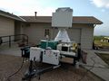
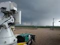
The pedestal is mounted to a 16 foot (5 m) trailer that may be towed by light vehicle. The picture above shows an overview of the trailer, with the phased array antenna mounted to the antenna positioner. The digital exciter/receiver mounted behind the antenna. To the right of the trailer are the weatherized enclosures with the signal processor and support equipment.
Road mobility allows testing and validation of the radar system in various locations and conditions. The radar trailer is self-contained and houses the radar electronics, signal processing hardware and data storage.
Scanning Strategies

|

|
| Electronic-scan in azimuth | Electronic-scan in elevation |
FrontX mounts the phased array antenna to a dual-axis mechanical positioner. The antenna array can be rotated about its boresight axis. This permits several scanning modes, including:
- 2D mechanical beam steering
- 1D electronic beam steering
- Azimuth scanning by default
- Elevation scanning by rotating the antenna by 90°
Software architecture

The FrontX radar system software is split into several modules, including hardware control modules (for each of the major radar subsystems), signal processing, data storage and display, and an overall system controller, which coordinates the actions of the other modules.
System controller

The system controller is responsible for receiving user commands and coordinating the operation of the other software and hardware subsystems. The user can specify radar tasks as an ordered list, which the controller executes in sequence. Each radar task contains a scanning mode description, along with the signal processor configuration items (radar timing (PRF), polarization mode, waveform, pulse compression filter).
Signal Processing
The DXR output is streamed over a 10 Gigabit Ethernet link to a compute server for further signal processing. This includes ground clutter filtering and parameter estimation using spectral processing algorithms and finally, applying calibration values to obtain meteorological product data. Both the processed as well as raw data are archived to a storage array for further analysis and display.
Example Data Collection
Tuesday, June 21, 2016
Weaker storm, scan strategy resulted in fairly blocky-looking images (256 integrations, 2kHz PRF, 64 beams per sweep). Waveform was set to 2.5 MHz, 10 us pulse width. Signal processor was programmed to compress this down to 60m range bins. A spectral notch filter was used to remove 3 bins around DC to suppress ground clutter. Each sweep is completed in 8 seconds.


|
|
||
|

Thursday, June 23, 2016
More developed storm, better scan strategy (128 integrations, 2kHz PRF, between 128 and 192 beams per sweep). There is some second-trip contamination in the first half of the data. Waveform was set to 2.5 MHz, 10 us pulse width. Signal processor was programmed to compress this down to 60m range bins. A spectral notch filter was used to remove 3 bins around DC to suppress ground clutter. Each sweep took between 8 to 12 seconds to complete (depending on total number of beams).


|
|
||
|

Friday, June 24, 2016
Small storm, same scan strategy as June 23 (128 integrations, 2kHz PRF, between 128 and 192 beams per sweep). Good SNR (> 30 dB) over most azimuths. Waveform was set to 2.5 MHz, 10 us pulse width. Signal processor was programmed to compress this down to 60m range bins. A spectral notch filter was used to remove 3 bins around DC to suppress ground clutter. Each sweep took between 8 to 12 seconds to complete (depending on total number of beams).
|
|
||
|

Gallery
-
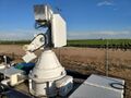
Front View of FrontX
-
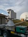
Side View of FrontX
-
Overview of FrontX trailer
-
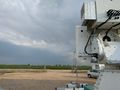
FrontX Operations on June 21, 2016
-
FrontX Operations on June 23, 2016
-
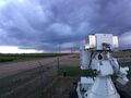
FrontX Operations on May 22, 2018


References
- J. George and V. Chandrasekar, "Front-X phased array weather radar test bed," 2016 IEEE International Symposium on Phased Array Systems and Technology (PAST), Waltham, MA, USA, 2016, pp. 1-7, doi: 10.1109/ARRAY.2016.7832547.
- A. Morin, J. George and V. Chandrasekar, "Polarimetric Calibration of a Dual-Polarization Phased Array Weather Radar," 2019 IEEE International Symposium on Phased Array System & Technology (PAST), Waltham, MA, USA, 2019, pp. 1-5, doi: 10.1109/PAST43306.2019.9020780.
- First RF Corporation website